Additive manufacturing (AM)
Introduction
Additive manufacturing (AM) is emerging to be one of the most promising advanced manufacturing processes. AM is a class of manufacturing process wherein the component is build up in a layer-by-layer manner. In the powder bed fusion (PBF) process, either a laser or an electron beam is used as the heat source to melt the powder, which is spread on the metallic substrate. Due to the specific advantages of design flexibility, rapid prototyping, and the ability to produce complex geometries.
AM industry is growing at a cumulative rate of 26% over the last 3 decades. However, the full potential of AM has yet to be realized because there are still many technical hurdles due to a lack of comprehensive knowledge of physical mechanisms. It is not always possible to capture these physical mechanisms with experiments as the process itself is instantaneous, and these mechanisms are active at different lengths and time scales.
At ICAMS, macroscopic and mesoscopic simulation models are used to study the complicated development of the microstructure during AM processes. We use the computational fluid dynamics (CFD) simulation
at macroscale to investigate the effect of process parameters on thermal evolution, melt flow dynamics and porosity. We apply the phase-field model (PF) at Mesoscale to understand nucleation phenomena, competitive grain
growth, dendritic arm spacings, and microsegregation.
OpenPhase Capabilities
We are currently developing advanced PF models for the rapid solidification process. The PF evolution equation is coupled to both heat diffusion and solute diffusion. We have redefined the heat diffusion
solver to accurately solve thermal evolution and release latent heat release at the dendritic scale. With the modified heat diffusion solver, it is also possible to apply external heat source boundary conditions (laser/electron
beam melting) generically to reproduce layer by layer material build-up. The solute diffusion is currently solved using a quasi-equilibrium approach that will be replaced with a finite interface dissipation model in the
near future. The nucleation model allows for nucleation of primary gamma and secondary gamma prime phases. Further, in situ homogenization, one of the key advantages of the AM process, is also possible with our
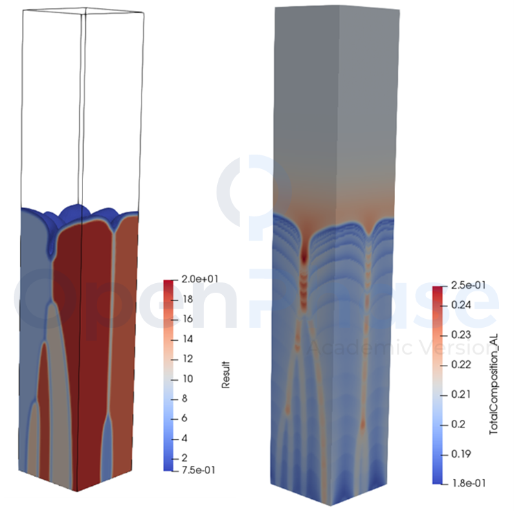
Figure 1: Microstructure evolution and solute seggregation in additive manufacturing obtained from phase-field simulations.
Simulation setup
Example: AdditiveNiAl
The OpenPhase® built-in example, "Superalloys" is used to model the evolution of gamma prime in the super-saturated gamma matrix. Interfacial, chemical, and mechanical free energy contributions are
included.
OpenPhase® has a built-in example, "AdditiveNiAl", to show you the solidification simulation during additive manufacturing for "NiAl-binary" system.
In order to run the simulation run "./AdditiveNiAl", and the results will be placed in the "VTK "directory and can be visualised using Paraview
The "ProjectInput.opi" contains the necessary input files for the simulation. The user can vary the file upon his particular use. The simulation conditions for the example shown here are considered as:
| Parameter | Symbol | Value | Units |
|---|---|---|---|
| Material system | - | Ni- 20 mol %Al | - |
| Grid Size | - | [121, 1, 241] | Cells |
| Grid spacing | Δx | 1 x 10 -7 | m |
| Time steps | Δt | 1 x 10 -7 | s |
| Interface width | η | 5Δx | m |
| Nucleation density | for 𝛾 in Liquid | 1 x 10 17 | m-3 |
| Grain boundary energy | σ | 0.24 | Jm-2 |
| Grain boundary mobility | μ | 1 x 10 -8 | m4(Js)-1 |
| Boundary conditions | PBCs | No Flux | - |
Results
Microstructure evolution during AM process
The below animation presents the microstructure evolution during initial solidification, remelting and subsequent solidification. The simulation started from a complete liquid state, and the only nucleation of γ is allowed in the liquid.
Figure 1: Results of phase-field evolution, composition of AL in liquid phase , temperature evolution and constitutional undercooling obtained for NiAl system with nucleation..
Recalescence phenomena
The figure presents the temperature evolution in the system during solidification. Thanks to the modified heat solve, we can accurately capture the recalescence phenomena (local temperature rise due to latent heat release).
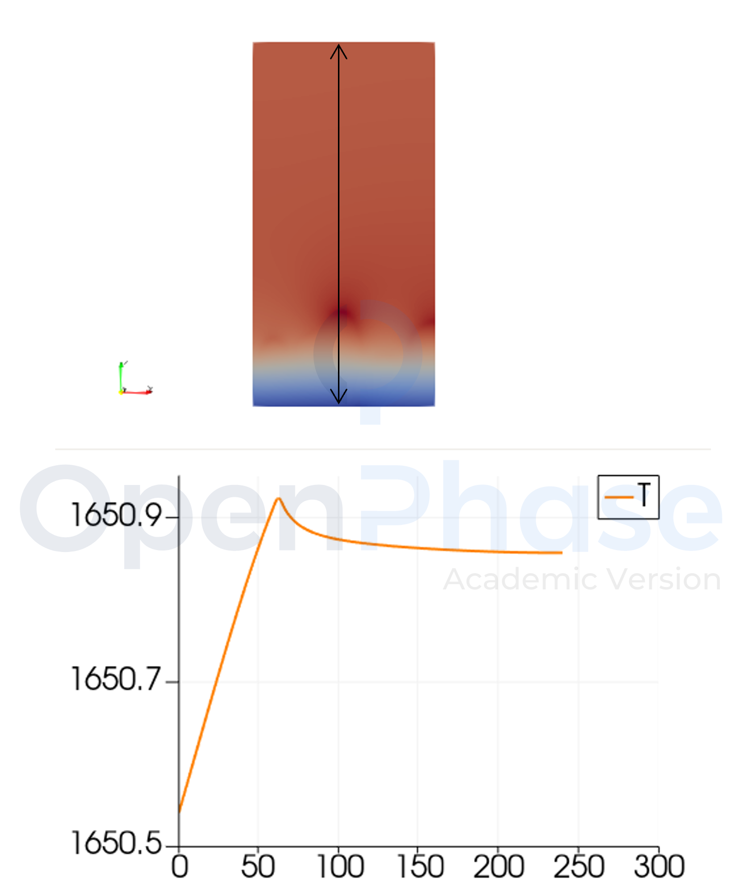
Figure 2: Temperature evolution obtained from the simulation results. The line scan highlights recalescence due to release of latent heat release in the system.
Related Topics